|
|
MLCC Production: Binder Removal and Sintering | |
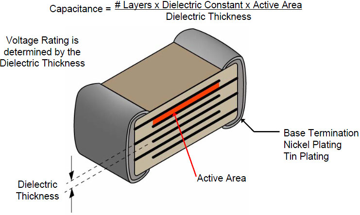
Multilayer Ceramic Capacitors (MLCCs) are among the most widely used and rapidly advancing basic components in the world, often referred to as the “rice of the industry.” They are crucial in the field of electronic components. The production process of MLCCs is intricate, involving several key stages such as material preparation, casting, screen printing, laminating, cutting, binder removal, high-temperature sintering, grinding and chamfering, termination, burn-in, electroplating, testing, and taping. Among these, binder removal and sintering are pivotal to the quality and performance of MLCCs. | Source:https://www.johansondielectrics.com | |
1. Binder Removal Process in MLCC Production
Binder removal is a thermal treatment process where organic binders like PVB resin and DOP, which are added to the ceramic powder for adhesion, are decomposed and expelled at specific temperatures. The purpose of binder removal is to prevent defects like delamination and cracking that can occur if organic materials volatilize rapidly during sintering. The main steps in binder removal include loading the green ceramic chips into trays, placing them into the binder removal furnace, and finally, removing them from the furnace.
Temperature, heating rate, and exhaust levels are crucial parameters:
- For MLCCs with nickel electrodes, binder removal is typically done in an air environment. Since nickel oxidizes above 300°C in air, the binder removal temperature is generally set between 250°C and 280°C, depending on the size and formulation of the MLCC. Binder removal in a nitrogen atmosphere allows for higher temperatures, around 400°C to 500°C.
- Copper, which oxidizes more easily than nickel, requires a high-temperature nitrogen environment to prevent oxidation during the binder removal process, ensuring the copper electrodes remain intact.
Despite the inert atmosphere, some organic material may remain, typically between 0.3% and 3.0%, requiring a pre-sintering step to further reduce carbon residues. This pre-sintering process heats the MLCC green body at a lower temperature than the final sintering, which helps to ensure the dielectric medium’s density and electrode continuity, enhancing the dielectric strength of the final product.
2. Sintering Process in MLCC Production
Sintering is the process where the ceramic body undergoes densification at specific temperatures, atmospheres, and pressures, resulting in a compact ceramic material with the desired mechanical and electrical properties. After binder removal, the sintering process transforms the green chip into a dense ceramic body with intact internal electrodes, qualified dimensions, high mechanical strength, and excellent electrical performance.
Sintering involves two key stages:
• Densification Stage: The MLCCs are placed in the furnace, where the sintering temperature typically ranges between 1100°C and 1350°C. To prevent oxidation, the furnace atmosphere is filled with gases like nitrogen or hydrogen. The critical aspect of sintering is maintaining uniform temperature and dynamic thermal balance within the furnace, ensuring that air flows freely to promote uniform grain growth and densification of the ceramic body.
• Reoxidation Stage: Ensures that the internal electrodes and the ceramic medium maintain their structural integrity during sintering. It is crucial to balance the oxygen partial pressure and temperature, as nickel can oxidize at high temperatures (>1200°C) if the oxygen partial pressure exceeds 10^-8 MPa, potentially leading to chip cracking. However, if the oxygen partial pressure is too low (<10^-14 MPa), the BaTiO3 medium may reduce, causing semiconductive behavior.
Impact of Binder Removal and Sintering on MLCC Quality
If the organic material in the MLCC chip is not fully decomposed before sintering, excess carbon residue can cause internal cracks, delamination, or fracturing during the rapid heating phase of sintering. Residual carbon negatively impacts the sintering process by hindering grain growth and reducing the density of the ceramic medium. Moreover, carbon can create localized reducing atmospheres, leading to agglomeration and fracture of the internal electrodes, ultimately affecting the reliability of the MLCC.
Key issues during sintering:
• Oxidation During Binder Removal: Nickel oxidation, although theoretically occurring at 280°C, can be controlled by the low oxygen concentration within the binder removal furnace, allowing the process to reach around 300°C. However, exceeding this temperature or inadequate oxygen levels can lead to oxidation, reducing MLCC capacity.
• Cracking During Binder Removal: Overloading trays, high temperatures, rapid heating rates, or insufficient equipment sealing can cause chips to crack during binder removal, reducing capacity.
• Oxidation, Delamination, and Cracking During Sintering: Differences in shrinkage rates between the internal electrodes and the ceramic medium, inadequate drying of the printed films, or insufficient binder removal can cause these defects. Rapid heating, low hydrogen content, or high oxygen partial pressure during the heating phase, excessive sintering temperature, or improper reoxidation conditions can lead to electrode oxidation, delamination, or cracking, affecting capacity and consistency.
For high-capacity products with thin dielectric layers (<3μm), these differences are even more pronounced. Rapid sintering processes (RHK) at rates like 25°C/min are often used to achieve co-sintering of the internal electrodes and dielectric medium, reducing electrode agglomeration and improving electrode continuity, thus enhancing product capacity.
Critical Sintering Challenges:
• Nickel Electrode Bleeding: This occurs when the sintering temperature exceeds the melting point of the internal electrode, and rapid heating or differential shrinkage between the ceramic body and the internal electrode leads to electrode bleeding.
• Residual Carbon: High residual carbon hinders grain growth and affects sintering densification. It can create localized reducing atmospheres, leading to electrode agglomeration and even reactions between carbon and nickel electrodes, reducing electrode continuity and capacity.
Sintering Temperature: If the pre-sintering temperature is too low (<800°C), excess residual carbon can affect electrode continuity. If the temperature is too high (≥900°C), the ceramic grains may become too dense during pre-sintering, blocking exhaust channels and leading to inadequate densification and reduced capacity during final sintering. Conversely, excessive sintering temperatures can cause over-shrinkage of the ceramic body, leading to high capacity but compromised structural integrity.
Conclusion:
The sintering atmosphere is crucial for MLCC electrical performance. Proper control of the sintering parameters—such as time, temperature, atmosphere, and oxygen partial pressure—is essential to achieve uniform, dense ceramic structures and maintain the electrical performance of MLCCs. Mismanagement can result in poor grain growth, inadequate densification, and reduced electrical properties. Conversely, overly aggressive sintering can lead to abnormal grain growth and the formation of additional crystalline phases, further degrading MLCC performance. Therefore, strict control of these parameters is vital to producing high-quality MLCCs.
|  | Source:https://ars.els-cdn.com | |
2. Sintering Process in MLCC Production
Sintering is the process where the ceramic body undergoes densification at specific temperatures, atmospheres, and pressures, resulting in a compact ceramic material with the desired mechanical and electrical properties. After binder removal, the sintering process transforms the green chip into a dense ceramic body with intact internal electrodes, qualified dimensions, high mechanical strength, and excellent electrical performance.
Sintering involves two key stages:
• Densification Stage: The MLCCs are placed in the furnace, where the sintering temperature typically ranges between 1100°C and 1350°C. To prevent oxidation, the furnace atmosphere is filled with gases like nitrogen or hydrogen. The critical aspect of sintering is maintaining uniform temperature and dynamic thermal balance within the furnace, ensuring that air flows freely to promote uniform grain growth and densification of the ceramic body.
• Reoxidation Stage: Ensures that the internal electrodes and the ceramic medium maintain their structural integrity during sintering. It is crucial to balance the oxygen partial pressure and temperature, as nickel can oxidize at high temperatures (>1200°C) if the oxygen partial pressure exceeds 10^-8 MPa, potentially leading to chip cracking. However, if the oxygen partial pressure is too low (<10^-14 MPa), the BaTiO3 medium may reduce, causing semiconductive behavior.
Impact of Binder Removal and Sintering on MLCC Quality
If the organic material in the MLCC chip is not fully decomposed before sintering, excess carbon residue can cause internal cracks, delamination, or fracturing during the rapid heating phase of sintering. Residual carbon negatively impacts the sintering process by hindering grain growth and reducing the density of the ceramic medium. Moreover, carbon can create localized reducing atmospheres, leading to agglomeration and fracture of the internal electrodes, ultimately affecting the reliability of the MLCC.
Key issues during sintering:
• Oxidation During Binder Removal: Nickel oxidation, although theoretically occurring at 280°C, can be controlled by the low oxygen concentration within the binder removal furnace, allowing the process to reach around 300°C. However, exceeding this temperature or inadequate oxygen levels can lead to oxidation, reducing MLCC capacity.
• Cracking During Binder Removal: Overloading trays, high temperatures, rapid heating rates, or insufficient equipment sealing can cause chips to crack during binder removal, reducing capacity.
• Oxidation, Delamination, and Cracking During Sintering: Differences in shrinkage rates between the internal electrodes and the ceramic medium, inadequate drying of the printed films, or insufficient binder removal can cause these defects. Rapid heating, low hydrogen content, or high oxygen partial pressure during the heating phase, excessive sintering temperature, or improper reoxidation conditions can lead to electrode oxidation, delamination, or cracking, affecting capacity and consistency.
For high-capacity products with thin dielectric layers (<3μm), these differences are even more pronounced. Rapid sintering processes (RHK) at rates like 25°C/min are often used to achieve co-sintering of the internal electrodes and dielectric medium, reducing electrode agglomeration and improving electrode continuity, thus enhancing product capacity.
Critical Sintering Challenges:
• Nickel Electrode Bleeding: This occurs when the sintering temperature exceeds the melting point of the internal electrode, and rapid heating or differential shrinkage between the ceramic body and the internal electrode leads to electrode bleeding.
• Residual Carbon: High residual carbon hinders grain growth and affects sintering densification. It can create localized reducing atmospheres, leading to electrode agglomeration and even reactions between carbon and nickel electrodes, reducing electrode continuity and capacity.
Sintering Temperature: If the pre-sintering temperature is too low (<800°C), excess residual carbon can affect electrode continuity. If the temperature is too high (≥900°C), the ceramic grains may become too dense during pre-sintering, blocking exhaust channels and leading to inadequate densification and reduced capacity during final sintering. Conversely, excessive sintering temperatures can cause over-shrinkage of the ceramic body, leading to high capacity but compromised structural integrity.
Conclusion:
The sintering atmosphere is crucial for MLCC electrical performance. Proper control of the sintering parameters—such as time, temperature, atmosphere, and oxygen partial pressure—is essential to achieve uniform, dense ceramic structures and maintain the electrical performance of MLCCs. Mismanagement can result in poor grain growth, inadequate densification, and reduced electrical properties. Conversely, overly aggressive sintering can lead to abnormal grain growth and the formation of additional crystalline phases, further degrading MLCC performance. Therefore, strict control of these parameters is vital to producing high-quality MLCCs.
|  | Source:https://cdn.everythingrf.com | |
Impact of Binder Removal and Sintering on MLCC Quality
If the organic material in the MLCC chip is not fully decomposed before sintering, excess carbon residue can cause internal cracks, delamination, or fracturing during the rapid heating phase of sintering. Residual carbon negatively impacts the sintering process by hindering grain growth and reducing the density of the ceramic medium. Moreover, carbon can create localized reducing atmospheres, leading to agglomeration and fracture of the internal electrodes, ultimately affecting the reliability of the MLCC.
| |
Key issues during sintering:
- Oxidation During Binder Removal: Nickel oxidation, although theoretically occurring at 280°C, can be controlled by the low oxygen concentration within the binder removal furnace, allowing the process to reach around 300°C. However, exceeding this temperature or inadequate oxygen levels can lead to oxidation, reducing MLCC capacity.
- Cracking During Binder Removal: Overloading trays, high temperatures, rapid heating rates, or insufficient equipment sealing can cause chips to crack during binder removal, reducing capacity.
- Oxidation, Delamination, and Cracking During Sintering: Differences in shrinkage rates between the internal electrodes and the ceramic medium, inadequate drying of the printed films, or insufficient binder removal can cause these defects. Rapid heating, low hydrogen content, or high oxygen partial pressure during the heating phase, excessive sintering temperature, or improper reoxidation conditions can lead to electrode oxidation, delamination, or cracking, affecting capacity and consistency.
- For high-capacity products with thin dielectric layers (<3μm), these differences are even more pronounced. Rapid sintering processes (RHK) at rates like 25°C/min are often used to achieve co-sintering of the internal electrodes and dielectric medium, reducing electrode agglomeration and improving electrode continuity, thus enhancing product capacity.
- Nickel Electrode Bleeding: This occurs when the sintering temperature exceeds the melting point of the internal electrode, and rapid heating or differential shrinkage between the ceramic body and the internal electrode leads to electrode bleeding.
- Residual Carbon: High residual carbon hinders grain growth and affects sintering densification. It can create localized reducing atmospheres, leading to electrode agglomeration and even reactions between carbon and nickel electrodes, reducing electrode continuity and capacity.
- Sintering Temperature: If the pre-sintering temperature is too low (<800°C), excess residual carbon can affect electrode continuity. If the temperature is too high (≥900°C), the ceramic grains may become too dense during pre-sintering, blocking exhaust channels and leading to inadequate densification and reduced capacity during final sintering. Conversely, excessive sintering temperatures can cause over-shrinkage of the ceramic body, leading to high capacity but compromised structural integrity.
| 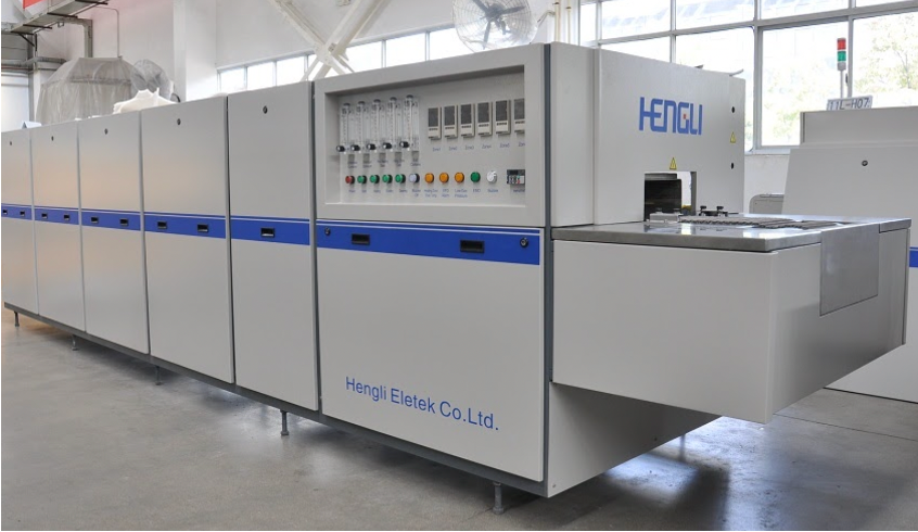 |  | |
Are you looking for an atmosphere belt furnace or a roller hearth kiln?
| |
Conclusion:
The sintering atmosphere is crucial for MLCC electrical performance. Proper control of the sintering parameters—such as time, temperature, atmosphere, and oxygen partial pressure—is essential to achieve uniform, dense ceramic structures and maintain the electrical performance of MLCCs. Mismanagement can result in poor grain growth, inadequate densification, and reduced electrical properties. Conversely, overly aggressive sintering can lead to abnormal grain growth and the formation of additional crystalline phases, further degrading MLCC performance. Therefore, strict control of these parameters is vital to producing high-quality MLCCs.
| |
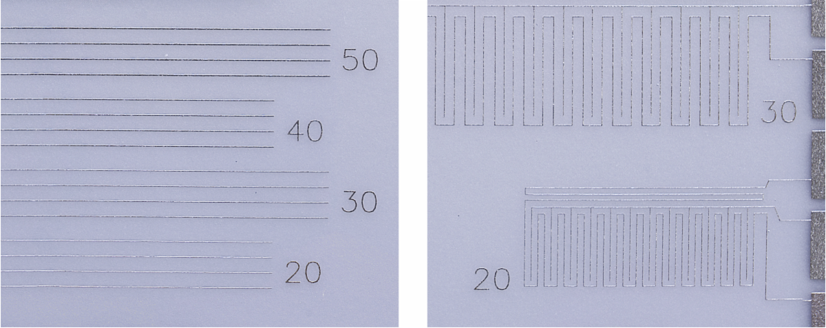
Screen Printer/ Screen Printing line
- Up to 20 μm with 100 μm standard
- 400*400 available
- Manual, auto, semi-auto available
| | |
|
If you want to learn more about our belt furnace, thick film product line, GTMS, LTCC and more,
please leave a message and click here.
| | | | |